
 Deutsch
How is it loaded?
Force, direction, attachments and repeated load cycles define the task. An assembly aid and a permanently load-bearing part need different evidence.
POLYMERS + FUNCTION
A material name alone does not describe a printed part. Orientation, layer bonding, temperature and geometry jointly determine its behaviour in service.
Force, direction, attachments and repeated load cycles define the task. An assembly aid and a permanently load-bearing part need different evidence.
Temperature, humidity, media exposure and service duration affect selection. Properties need to match the actual use.
Build orientation, toolpath and local geometry affect layer bonding. Reinforced polymers can also behave differently by direction.
The paths within each layer and the bonds between layers create a structure inside the part. Direction-dependent behaviour is called anisotropy: the same material can respond differently along and across the build.
Design benefit: compare orientations against loads, interfaces and manufacturing conditions. The animated paths are process information, not proof of achieved strength.
Problem: an FDM air duct warps, so its nominal geometry does not describe its final shape.
Approach: This application example compares a Digimat-AM process simulation with three actual scans of parts printed in ULTEM 9085 CG. The images show similar spatial warpage patterns, without establishing a universal accuracy percentage.
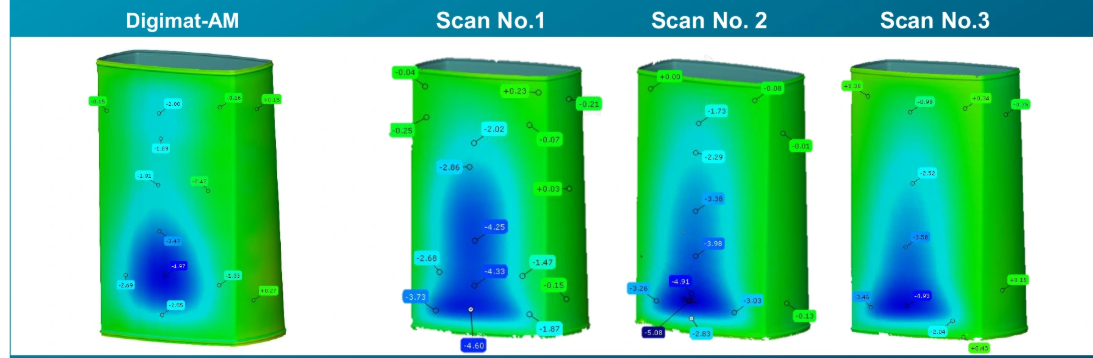
Benefit: identify critical regions before manufacture and plan comparison with suitable measurement data. ULTEM in this example is not an additional shop material offer.
Digimat multiscale models describe how material structure and manufacturing information can feed into part analysis. Fibre orientation and print direction matter for reinforced polymers; voids between deposited beads can affect behaviour too.
For each project, we assess available properties, material models and process data and select a suitable analysis method. Tests representative of the actual material and build are preferable to unverified data transferred from a different printing process.
UNIKE offers PEEK, PPS and multi-material printing. Selection follows the function and operating conditions. Rigid and flexible combinations also require attention to interfaces, transitions and assembly.
Send a CAD model or drawing, intended material, quantity, loads and attachments, temperature range and critical dimensions. If a part has failed, describe the failure location and operating conditions. We will agree any additional data needed.
Tell us the material, process, quantity, loads and critical dimensions. An existing problem such as warpage or a failed connection is a useful starting point. We agree the engineering scope and deliverables for your project.